BASIC PRINCIPLE, TYPES AND CONSTRUCTIONAL FEATURES OF ELECTRIC MACHINES
There are three basic rotating electric machine types, namely
1. the dc machine,
2. the polyphase synchronous machine (ac),
3. the polyphase induction machine (ac).

|
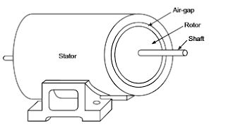
Three materials are mainly used in machine manufacture; steel to conduct magnetic flux, copper (or aluminum) to conduct electric current and insulation to insulate the voltage induced in conductors confining currents to them. All electric machines comprise of two parts: the cylindrical rotating member called the rotor and the annular stationary member called the stator with the intervening air-gap as illustrated The rotor has an axial shaft which is carried on bearings at each end located in end covers bolted to the stator. The shaft extends out of the end cover usually at one end and is coupled to either the prime mover or the load. The stator and rotor are both made of magnetic material (steel) which conducts the magnetic flux upon which depends the process of energy conversion. In both dc and synchronous machines, the main field is created by field poles excited with direct current. The winding on the field poles is called the field winding. The relative motion of the field past a second winding located in the other member induces emf in it. The winding interchanges current with the external electric system depending upon the circuit conditions. It is this winding, called the armature winding, which handles the load power of the machine, while the field winding consumes a small percentage (0.5% to 2%) of the rated load power. The load dependent armature current is known as load current.
In a dc machine the field poles are on the stator while the rotor is the armature as shown in the crosssectional view of Fig. 1.5. The field poles are symmetrical and are even in number, alternately north and south. As the armature rotates, alternating emf and current induced in the armature winding are rectified to dc form by a rotating mechanical switch called the commutator, which is tapped by means of stationary carbon brushes. The commutator is cylindrical in shape and comprises severel wedge-shaped copper segments
representation of a transformer and p shows a simple electric power generation transmission and reception system. A practical electric power system is an integrated one, far more complex than the simple diagrammatic representation and is in the form of an interconnected network for reasons of economy, operational efficiency and reliability. Because the principle of rotating ac machines is akin to that of a transformer, these two are always studied together in a book. Further, since the transformer analogy can be extended to both the ac machine types, the transformer study usually precedes the machine study.
Stator
Air-gap
Rotor
Shaft
bound together while they are insulated from each other. The armature is made of laminated steel with slots cut out on the periphery to accommodate the insulated armature winding. The ends of each armature coil are connected to the commutator segments to form a closed winding. The armature when carrying current produces stationary poles (same as number of field poles) which interact with the field poles to produce the electromagnetic torque.
In a synchronous machine the field poles could be either on the stator or rotor, but in all practical machines the rotor carries the field poles as shown in the cross-sectional view .The field poles are excited by direct current. The stator forms the armature carrying a 3-phase winding wound for the same number of poles as the rotor. All the three phases have identical windings with the same angular displacement between any pair of phases. When the rotor rotates, it produces alternating emf in each phase forming a balanced set with frequency given by
f = nP 120 (1.1)
where f = frequency in Hz
n = rotor speed in rpm
P = number of field poles
For a given number of poles, there is a fixed correspondence between the rotor speed and the stator frequency; the rotor speed is therefore called the synchronous speed. When balanced 3-phase currents are allowed to flow in the armature winding, these produce a synchronously rotating field, stationary with respect to the rotor field as a result of which the machine produces torque of electromagnetic origin. The synchronous motor is, however, non self starting. In both dc and synchronous machines the power handling capacity is determined by the voltage and current of the armature winding, while the field is excited from low power dc. Thus these machine types are doubly excited. Quite different from these, an induction machine is singly excited from 3-phase mains on the stator side. The stator winding must therefore carry both load current and field-producing excitation current. The stator winding is 3-phase, similar to the armature winding of a synchronous machine. When excited it produces a synchronously rotating field.
Two types of rotor constructions are employed which distinguish the type of induction motor.
1. Squirrel-cage rotor :- Here the rotor has copper (or aluminum) bars embedded in slots which are short-circuited at each end . It is a rugged economical construction but develops low starting torque.
2. Slip-ring (or wound-rotor) rotor :-The rotor has a proper 3-phase winding with three leads brought out through slip-rings and brushes .These leads are normally short-circuited when the motor is running. Resistances are introduced in the rotor circuit via the slip-rings at the time of starting to improve the starting torque.


No comments:
Post a Comment