Monday 10 May 2021

What is Digital transducer or smart transducer ?

 A transducer that measure physical quantities and transmit the information as coded digital signals rather than as continuously wearing current or voltage is called digital transducer.

As sensors and actuators become more complex they provide support for various modes of operation and interfacing. Some application requires additional e fault tolerance and distributed computing. Search high level functionality can be achieved by adding an embedded microcontroller to the classical sensor/actuator which increases the ability to cope with the complexity at a fair price. Does integration of an analogue or digital sensor or actuator a processing unit and a communication become necessary.

Transducer are sensors and actuator in order that a computer system can interact with the physical environment. In 1982, KO and Fung introduce the term "intelligent transducer". An intelligent trans ducer for smart transducer is the integration of an analogue or digital sensor actuator element a processing unit and communication interface. In case of a sensor the smart transducer transform the raw sensor signal to a standardized digita representation of check and calibrate the signal and transmit this signal to its user via a standardized communication protocol. In case of any actuated the smart of ducer except standardized amounts and transforms this into control signals for the actuator. Interface is a referred to as water transducer for signal transducer.


Friday 30 April 2021

The beginning of the universe.

 The beginning of the universe had, of course, being discussed for a long time. According to a number of early e cosmologist in the the Russian / Muslim / Christian tradition, the universe started at a finite and not very distant time in the past. One argument for search a beginning was the feeling that it was necessary to have a fast cause to explain the the existence of universe.

Another argument was put forward by St. Augustine in his book 'the city of God'. He pointed out that civilization is progressing and we remember who performed distilled o developed that technique. Bus man and so also perhaps the universe could not have been rounded all that long for otherwise we would have already progressed more than we have.

Sent Augustine accepted a date of about 5000 BC e for the creation of the universe according to the book of genesis it is interesting that this is not so far from the end of the last ice age about 10000 BC which is when civilization really begin Aristotle and most of the other Greek philosophers on the other hand did not like the idea of a creation because it made too much of divine intervention they believed therefore that the human race and the world around it had existed and would exist forever.

They had already considered the argument about progressive described earlier and answered it by saying that there had been product flood or other disasters that repeatedly said the human race right back to the beginning of civilization.

When most people believe in an essentially static and I'm changing universe the question of whether or not it had a beginning was really one offer metaphysics for theology one could account for what was observed in the way either the universe had existed forever for it was set in motion at some finite time in which a manner as to look as through it held existed forever but in 1929 Edwin Hubble made the landmark observation that wherever you look distant stars are moving rapidly away from us in other words the universe is expanding this means that at earlier time objects would have been closer together in fact it seemed that there was at time about 10 or 20 thousand million years ago when they were all at exactly the same place.

This discovery finally brought the question of the beginning of the universe into the realm of science. Hubble's observations suggested that there was a time call the Big Bank when the universe was infinite lists small and therefore infinitely dense they were events earlier than this time then they could not effective what happened at the present time their existence can be ignored because at would have no observational consequences.

One may say that time had a beginning at the big bang in the sense that earlier times simply could not be defined it should be emphasized that this beginning in in time is very different from those that had been considered previously in an unchanging universe a beginning in time is some thing that has to be imposed by some being outside the universe there is no physical necessity for beginning one can imagine that god created the universe at literally and time in the past on the other hand if the universe is expanding their main physical regions why there had to be beginning one could not believe that god created the universe at the instant of the big bang he could even have created it at a later time in just such a way as to make it look like through there had been a big bang but it would be meaningless to suppose that it was created before the big bang an expanding universe does not preclude a creator but it does place limits on when he might have a carried out his job.

Source:- The theory of everything by Stephen w Hawking.

Thursday 29 April 2021

Difference between microprocessor and microcontroller hand written notes

 Difference between microprocessor and microcontroller

Microprocessor

  • It consists a l u , c u and resistors.
  • No internal memory.
  • No interfacing circuits like timer and counters.
  • यूज्ड फॉर जनरल परपज ऑपरेशंस एंड एप्लीकेशंस
  • Examples intel  8050 , 8086 ,...,i7 ,i8
  • It follows Van Neuman Architecture.
  • Program and data stored at same place.
  • CPU is stand alone as RAM,ROM, INPUT/OUTPUT, TIMER ETC are separated.

MICROCONTROLLER

  • It also purchased of a l u, cu and register.
  • Contains internal memory.
  • Contents interfacing circuits like timers and counters etc.
  • Examples 8051 PIc8
  • Used for specific over a particular application.
  • It follows forward architecture.
  • Data and programs are stored in different places.
Central processing unit ,Ram ,ROM ,input and output unit and timers for on single chip.


Friday 11 December 2020

WHAT IS ALTERNATOR AND SYNCHRONOUS GENERATOR?

What is alternator and synchronous generator 

 An alternator consists of two parts, the stator, and the rotor. The stator is the stationary part of the machine, and the rotor is the rotating part of the machine. The stator carries the armature winding in which the voltage is generated, and the output is taken from it. The rotor of the machine produces the main flux.

Stator Construction

The parts of the stator are the frame, stator core, stator windings, and cooling arrangement. The frame of the stator is made up of cast iron for a small-size machine, and welded steel for large size machines. To reduce the hysteresis and eddy current losses, the stator core is assembled with high-grade silicon content steel laminations. A 3-phase winding is put in the slots cut on the inner periphery of the stator. The winding is star connected and is distributed over several slots. When current flows in a distributed winding it produces an essentially sinusoidal space distribution of e.m.f.


Rotor Construction

The rotor construction is of two types


Salient-pole type.

Cylindrical rotor type.

Construction of three phase synchronous machines


Salient-pole rotor

The term salient means 'projecting'. A salient-pole consists of poles that are projected out from the surface of the rotor core. These are used for the rotors for four or more poles.


The rotor is subjected to changing magnetic fields that is why it is made of steel laminations to reduce the eddy current losses. Identical dimensions poles are assembled by stacking laminations to the required length and then riveted together. After the field coil is placed around each pole body, these poles are fitted by a dove-tail joint to a steel spider keyed to the shaft. Salient-pole rotors have faces to damp out the rotor oscillations during a sudden change in load conditions. A non-uniform air gap accompanies a salient-pole synchronous machine.


The air gap is minimum under the pole centers, and it is maximum in between the poles. The pole faces are so shaped that the radical air gap length increases from the pole center to the pole tips so that the flux distribution in the air gap is sinusoidal. This will help the machine to generate sinusoidal e.m.f.


To give the alternate north and south polarities, the individual field-pole windings are connected in series. The end of the field windings is connected to a d.c winding by the brushes on the slip-rings.


The salient-pole generators have a large number of poles and lower operating speed. Salient-pole alternators that are driven by water turbines are called hydro-alternators or hydro generators.


Cylindrical Rotor

Cylindrical-rotor machines are also known as non-salient pole rotor machine. The construction of the rotor is such that it forms a smooth cylinder. It has no physical poles as in the salient-pole construction. These rotors are made up of solid forgings of high-grade nickel-chrome-molybdenum steel.


In about two-thirds of the rotor periphery, slots are cut at regular intervals and parallel to the shaft.


The d.c field windings are connected in these slots. The winding is of distributed type. The unslotted portion of the rotor forms two pole faces. These machines have a small diameter and long axial length.


Such construction limits the centrifugal forces. Thus, the cylindrical rotors are useful in high-speed machines.


Steam or gas turbines drive Cylindrical-rotor machines. Cylindrical-rotor synchronous generators are called turbo-alternators or turbo-generators.

Thursday 10 December 2020

what is V-Curve of synchronous motor ?

what is V-Curve of synchronous motor?

 Curves of armature current vs. field current (or excitation voltage to a different scale) are called V curves and for typical values of synchronous motor loads. The curves are related to the phasor diagram and illustrate the effect of the variation of field excitation on armature current and power factor for typical shaft loads. It can be easily noted from these curves that an increase in shaft loads require an increase in field excitation in order to maintain the power factor at unity

the graph plotted between field current and armature current is known as the V curve. since the shape of this curve is looks like v in shape so this curve is known as v curve.

Handwritten notes are below


Saturday 31 October 2020

duckduckgo search


duckduckgo private search engine
source:- internet
DuckduckGo is a web browser. It is used world wide. It is popular due to its private browsing. You can search privately in DuckduckGo search . 
Chrome extension is available for desktop.
Mobile application and pc application are also available.
Some features of DuckduckGo web browser:-
1. Private browsing
2. Less memory
3. Multiple windows or tab
4. Use search engine that does not track you
5. They ensure that they don't sell your personal data
6. Inbuilt download manager
7. Fast reloading

Thursday 29 October 2020

What is corona effect in electrical engineering ?

 What is corona effect in electrical engineering ? 

corona effect
corona effect
                  Image source:- slide share

Crown is a glowing, perceptible release that happens when there is an unnecessary confined electric field inclination upon an article that causes the ionization and conceivable electrical breakdown of the air contiguous this point. Crown is portrayed by a hued sparkle often noticeable in an obscured climate. The discernible release, normally an inconspicuous murmuring sound, increments in power with expanding yield voltage. Ozone, a putrid, precarious type of oxygen is as often as possible created during this cycle. Elastic is crushed by ozone, and nitric corrosive can be made if adequate dampness is available. These things have negative effects on materials, comprehensive of electrical covers. 


A decent high voltage configuration considers crown age and gives plan countermeasures to restrict the chance of issues creating. Spellman engineers utilize modern e-field displaying programming and a Biddle Halfway Release Identifier to guarantee that every high voltage configuration doesn't have unreasonable field slopes, forestalling incomplete release and crown age.

Thursday 22 October 2020

what are the different types of ac supply ?


what is Magnetic Field ?

                Magnetic Field


Whenever a current flows through

a conductor, a magnetic field is

established around that conductor.

what is  Magnetic Field ?

  the cross-sectional

views of two conductors carrying

current in opposite directions. The

cross sign (¥) shown inside the

conductor indicates that current is

entering the conductor whereas the

dot sign (◊) shown indicates that the

current is coming out in a direction

perpendicular to the plane of the paper. Directions of flux lines around the conductors

are also shown in the figure. The direction of the lines of force around a conductor

is readily determined by the right-hand rule which is as follows—point the thumb

of the right hand in the direction of the current in the conductor and wrap the fingers

of the right hand around the conductor. The finger tips will point in the direction of

the lines of force.

The cork screw rule can also be applied to determine the direction of the lines of

force around a current-carrying conductor.

Concentration of flux can be produced by causing the current to flow through

a coil instead of through a conductor. Inside the coil the flux contributed by each

segment of the coil is in the same direction. Thus a strong magnetic field is produced

due to current fl owing through a coil. The introduction of a

magnetic material as a core for the coil increases the flux. A simple right-hand rule

indicates the direction of magnetic flux inside a coil: Wrap the fingers of the right

hand around the coil, with the finger tips pointing in the direction of the current, the

thumb points in the direction of the magnetic flux.

Wednesday 21 October 2020

BASIC PRINCIPLE, TYPES AND CONSTRUCTIONAL FEATURES OF ELECTRIC MACHINES

  BASIC PRINCIPLE, TYPES AND CONSTRUCTIONAL FEATURES OF ELECTRIC MACHINES 

There are three basic rotating electric machine types, namely 

 1. the dc machine, 

 2. the polyphase synchronous machine (ac), 

 3. the polyphase induction machine (ac).

machine


 Three materials are mainly used in machine manufacture; steel to conduct magnetic flux, copper (or aluminum) to conduct electric current and insulation to insulate the voltage induced in conductors confining currents to them. All 
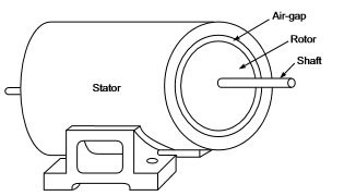
electric machines comprise of two parts: the cylindrical rotating member called the rotor and the annular stationary member called the stator with the intervening air-gap as illustrated The rotor has an axial shaft which is carried on bearings at each end located in end covers bolted to the stator. The shaft extends out of the end cover usually at one end and is coupled to either the prime mover or the load. The stator and rotor are both made of magnetic material (steel) which conducts the magnetic flux upon which depends the process of energy conversion. In both dc and synchronous machines, the main field is created by field poles excited with direct current. The winding on the field poles is called the field winding. The relative motion of the field past a second winding located in the other member induces emf in it. The winding interchanges current with the external electric system depending upon the circuit conditions. It is this winding, called the armature winding, which handles the load power of the machine, while the field winding consumes a small percentage (0.5% to 2%) of the rated load power. The load dependent armature current is known as load current. 

dc machine

In a dc machine the field poles are on the stator while the rotor is the armature as shown in the crosssectional view of Fig. 1.5. The field poles are symmetrical and are even in number, alternately north and south. As the armature rotates, alternating emf and current induced in the armature winding are rectified to dc form by a rotating mechanical switch called the commutator, which is tapped by means of stationary carbon brushes. The commutator is cylindrical in shape and comprises severel wedge-shaped copper segments 

representation of a transformer and p shows a simple electric power generation transmission and reception system. A practical electric power system is an integrated one, far more complex than the simple diagrammatic representation  and is in the form of an interconnected network for reasons of economy, operational efficiency and reliability.  Because the principle of rotating ac machines is akin to that of a transformer, these two are always studied together in a book. Further, since the transformer analogy can be extended to both the ac machine types, the transformer study usually precedes the machine study.

Stator

Air-gap

Rotor

Shaft

bound together while they are insulated from each other. The armature is made of laminated steel with slots cut out on the periphery to accommodate the insulated armature winding. The ends of each armature coil are connected to the commutator segments to form a closed winding. The armature when carrying current produces stationary poles (same as number of field poles) which interact with the field poles to produce the electromagnetic torque.

synchronous machine

In a synchronous machine the field poles could be either on the stator or rotor, but in all practical machines the rotor carries the field poles as shown in the cross-sectional view .The field poles are excited  by direct current. The stator forms the armature carrying a 3-phase winding wound for the same number of poles as the rotor. All the three phases have identical windings with the same angular displacement between any pair of phases. When the rotor rotates, it produces alternating emf in each phase forming a balanced set with frequency given by

 f = nP 120 (1.1) 

where f = frequency in Hz

 n = rotor speed in rpm

 P = number of field poles

 For a given number of poles, there is a fixed correspondence between the rotor speed and the stator frequency; the rotor speed is therefore called the 
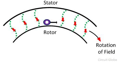
synchronous speed. When balanced 3-phase currents are allowed to flow in the armature winding, these produce a synchronously rotating field, stationary with respect to the rotor field as a result of which the machine produces torque of electromagnetic origin. The synchronous motor is, however, non self starting. In both dc and synchronous machines the power handling capacity is determined by the voltage and current of the armature winding, while the field is excited from low power dc. Thus these machine types are doubly excited. 
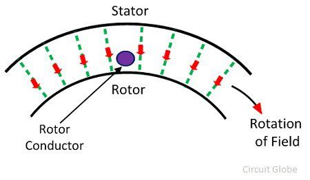
Quite different from these, an induction machine is singly excited from 3-phase mains on the stator side. The stator winding must therefore carry both load current and field-producing excitation current. The stator winding is 3-phase, similar to the armature winding of a synchronous machine. When excited it produces a synchronously rotating field. 

Two types of rotor constructions are employed which distinguish the type of induction motor. 

1. Squirrel-cage rotor :- Here the rotor has copper (or aluminum) bars embedded in slots which are short-circuited at each end . It is a rugged economical construction but develops low starting torque. 

2. Slip-ring (or wound-rotor) rotor :-The rotor has a proper 3-phase winding with three leads brought out through slip-rings and brushes .These leads are normally short-circuited when the motor is running. Resistances are introduced in the rotor circuit via the slip-rings at the time of starting to improve the starting torque.

Sunday 18 October 2020

what is The Differences in AC Current vs DC Current ?


Direct current, developed by Thomas Edison and the standard of America’s early foray into the world of electricity, involves the use of current that runs in a single direction. Unfortunately, its inability to be easily converted into higher/lower voltages led others to look to alternative solutions: Namely Nikola Tesla’s AC current. Alternating and reversing direction 60 times per second (50 in Europe), AC current could be converted to different voltages more easily using a transformer. The “War of the Currents” ensued as the inventors battled for relevance (and royalties) in the future of America’s electrical infrastructure. In the end George Westinghouse partnered with Tesla, leading AC into American homes nationwide. However, in recent years, DC has seen a bit of a renaissance. Why?


Application Powers the Need for AC vs DC Current

While both AC and DC current deliver electricity, the way in which that electricity arrives at its end destination differs. What are your appliances and electronics eating?

  • AC
    Your home or office receives electricity in the form of wave-like AC current, which is capable of changing direction and voltage from higher to lower current with the aid of transformers. In your home it is eaten by corded appliances small and large, from your HVAC to your TV and dishwasher.
  • DC
    The consistent and constant voltage of DC power supplies electronics that use a battery, such as your mobile device or smartphone. Like the battery powering your kid’s remote control car, the smooth, steady electrical current of DC power always flows in the same direction, between positive and negative terminals.
  • AC/DC
    Your laptop uses a combination of both types of electric current, beginning with AC from the outlet to your charging cord, to be converted into DC via the bulky little box (a power adapter) between the outlet and the end that plugs into your computer to recharge the battery. Some vehicles likewise use a combination of AC/DC current.

Working Principle And Types Of An Induction Motor

            Working Principle And Types Of An Induction Motor

Induction Motors are the most commonly used motors in many applications. These are also called as Asynchronous Motors, because an induction motor always runs at a speed lower than synchronous speed. Synchronous speed means the speed of the rotating magnetic field in the stator.

There basically 2 types of induction motor depending upon the type of input supply - (i) Single phase induction motor and (ii) Three phase induction motor.

Or they can be divided according to type of rotor - (i) Squirrel cage motor and (ii) Slip ring motor or wound type


induction motor

Basic Working Principle Of An Induction Motor

In a DC motor, supply is needed to be given for the stator winding as well  as the rotor winding. But in an induction motor only the stator winding is fed with an AC supply.
  • Alternating flux is produced around the stator winding due to AC supply. This alternating flux revolves with synchronous speed. The revolving flux is called as "Rotating Magnetic Field" (RMF).
  • The relative speed between stator RMF and rotor conductors causes an induced emf in the rotor conductors, according to the Faraday's law of electromagnetic induction. The rotor conductors are short circuited, and hence rotor current is produced due to induced emf. That is why such motors are called as induction motors
    (This action is same as that occurs in transformers, hence induction motors can be called as rotating transformers.) 
  • Now, induced current in rotor will also produce alternating flux around it. This rotor flux lags behind the stator flux. The direction of induced rotor current, according to Lenz's law, is such that it will tend to oppose the cause of its production. 
  • As the cause of production of rotor current is the relative velocity between rotating stator flux and the rotor, the rotor will try to catch up with the stator RMF. Thus the rotor rotates in the same direction as that of stator flux to minimize the relative velocity. However, the rotor never succeeds in catching up the synchronous speed. This is the basic working principle of induction motor of either type, single phase of 3 phase. 

Synchronous Speed:

 The rotational speed of the rotating magnetic field is called as synchronous speed.
Snchronous speed Ns=120f/P
where, f = frequency of the spply
            P = number of poles

Slip:

Rotor tries to catch up the synchronous speed of the stator field, and hence it rotates. But in practice, rotor never succeeds in catching up. If rotor catches up the stator speed, there wont be any relative speed between the stator flux and the rotor, hence no induced rotor current and no torque production to maintain the rotation. However, this won't stop the motor, the rotor will slow down due to lost of torque, the torque will again be exerted due to relative speed. That is why the rotor rotates at speed which is always less the synchronous speed.
The difference between the synchronous speed (Ns) and actual speed  (N) of the rotor is called as slip.
slip in induction motor

Why Rotor never runs at Synchronous Speed?


Why Rotor never runs at Synchronous Speed?

If the speed of the rotor is equal to the synchronous speed, no relative motion occurs between the rotating magnetic field of the stator and the conductors of the rotor. Thus the EMF is not induced on the conductor, and zero current develops on it. Without current, the torque is also not produced.

Because of the above mention reasons the rotor never rotates at the synchronous speed. The speed of the rotor is always less than the speed of the rotating magnetic field.

Alternatively, the method of the working principle of Induction Motor can also be explained as follows.

Let’s understand this by considering the single conductor on the stationary rotor. This conductor cuts the rotating magnetic field of the stator. Consider that the rotating magnetic field rotates in the clockwise direction. According to Faraday’s Law of electromagnetic induction, the EMF induces in the conductor.

As the rotor circuit is completed by the external resistance or by end ring, the rotor induces an EMF which causes the current in the circuit. The direction of the rotor induces current is opposite to that of the rotating magnetic field. The rotor current induces the flux in the rotor. The direction of the rotor flux is same as that of the current.


The interaction of rotor and stator fluxes develops a force which acts on the conductors of the rotor. The force acts tangentially on the rotor and hence induces a torque. The torque pushes the conductors of the rotor, and thus the rotor starts moving in the direction of the rotating magnetic field. The rotor starts moving without any additional excitation system and because of this reason the motor is called the self-starting motor.

The operation of the motor depends on the voltage induced on the rotor, and hence it is called the induction motor.